Minggu, 31 Juli 2016

Plywood!!! Okoume BS 1088 throughout


I bit the bullet today and ordered my plywood from Boulter Plywood in Sommerville, MA.  I called at 2:00 PM and by 3:00 PM the driver was calling to tell me I could have it by 3:30PM!!!  Incredible.
Unfortunately, I am not home....

Total bill was $1140.  So, I guess I am not buying a large screen TV this month.  With care this boat should last for a generation or two.  9 Sheets of 6mm,  3 sheets of 9 mm.

I will actually be boatbuilding by tomorrow!!!


Read More..

Sabtu, 30 Juli 2016

Methane Vents


As  permafrost melts, it releases methane. The methane exits the permafrost via vents which until recently were  small like the one pictured  but in the past year have increased in size to hundreds of feet across.  Careful when you light a cigarette.

Forget the effect of CO2 in the atmosphere on the temperature of the earth.  Methane is the gas du jour because it is 26 times as good an insulator as CO2.  CO2 is merely a gateway gas that sets us up for methane, the really bad stuff.  If you think where you live isnt warm enough, methane is the answer.  A little video here. I am providing a link since the blogger cant be embed flash videos. So flare away.
Actually, we did need to increase the CO2  in the atmosphere to the point where the Arctic was warm enough to release methane on its own accord.  We seem to be there now. Each year promises more melting in the Arctic and further release of methane. So CO2 did its part and can now step into the background.
What does this have to do with skinboats?  Nothing really other than that their use has very little effect on either CO2 or methane concentrations in the atmosphere.  Skinboats, in the current lingo are practically carbon neutral or can be made to be carbon neutral with some effort.  On the other hand, using skinboats does nothing to reduce the release of methane into the atmosphere and though it isnt hurting things, it isnt helping either.

Read More..

Kamis, 28 Juli 2016

It has been a very long and cold winter in New England.  Working outdoors to do planing, shaping, and fairing of the blades has been impossible due to the weather and family/work schedule.  I have put in for retirement, so time to work on the boat is not far away.  The weekly 60 hour work week gets in the way of these important things.

today - assembled the rudder head stock, and fitted the shaped blade.  Nothing fancy on the shaping,  I simply planed and sanded a reasonable shape to the flat stock so that the thickest sections were about 1/3 back.  Will coat with epoxy and paint when the days get longer and warmer.
Builders of a CS 17 should note that the leading edge of the rudder protrudes slightly forward of the head stock.  When the pintles are added, it will be in line with the pivot point.  


yup, Its snug, but wont take much to loosen up.  A little sanding and then prime and paint.  


Centerboard shaping - 
From the blank, I attached a NACA 0006 series template to the end of the tip and drew a line around the tip.  Then I set up the router to rout grooves to the depth indicated on the template up and down each side.  

template is sitting on the blade, was attached to the tip.  radial lines kept to the ratio were then scribed on the blade and a guide for the router set up. 

Not bad for a first attempt.  A few low spots and some high spots still, but fixable.  the router and electric plane made short work of this.  Then followed up with the wood eraser (7" disc grinder), and palm sander.  


Leading edge needs some attention, and I still need to shape the tip.  Not quite sure what I am going to do here.  Just a simple rounding over?  When the board is raised partially, this will also be a quasi trailing edge.  


Read More..

The Utility part 6 Fixing the chines

I made a common mistake when I installed the chines. Sure, Id read about the possibility of making this mistake beforehand. However, I obviously didnt "get" it. Happily, its a common mistake with a fairly simple fix. Im going to share all this with you in hopes that the new builder might avoid this pitfall.

The mistake is: not getting enough twist in the forward section of the chine log.

The resulting problem is: inadequate twist in the forward section of the chine leaves you with NO SURFACE AREA for the side planking to mate to.

Heres an image to help illustrate:


You see, after the chine and sheers are installed, both of these pieces are faired. The forward section of the chine is basically beveled along a line running down the middle of the wood from the stem to the forward frame. The upper (top-side) section of this bevel is where the lower edge of the side planking will attach. The top-side edge of the planking will attach to the sheer (shown as the dashed white line in the photo).

If you do not put an adequate twist in the forward section of the chine, then the resulting angle will not point outward adequately to the sheer line. This problem is illustrated by the dashed red line in the photo.

To avoid this problem, be sure to twist the chine adequately in the direction shown by the green arrows before you permanently attach the chine to the stem & frames. I did not twist mine adequately, because I thought the wood was going to break. So what. Soak it, steam it.... whatever you have to do to make it twist enough. Otherwise, youre going to have a problem to fix — just like I did.

The Fix:

The fix is: add a wedge-shaped strip along the top-side half of the forward chine, so that youll have an adequate angle toward the sheer & enough surface area to attach the planking to after fairing.

The Utilitys chines are 2 inches wide. The distance from the tip of the stem to the forward frame is 4 feet. So, I ripped two 1-inch by 4-foot sections of wood from the remnants of my first chine log (which broke because I didnt steam it).

I placed a straight edge from the chine to the sheer, and measured the angle. I then beveled my new "chine strips" so they would angle 20 degrees outward from the surface of the installed chine log. The resulting strips were fairly thin.

Cross-section of the "chine strip" after beveling it 20° on a planer / jointer.
I then epoxied these strips onto the top-side half of the forward chine. They were a little long, so I had to trim them. They bent easily since they were so thin. Now, I should have an adequate surface area for fairing & attaching the side planking.

Forward end of the attached chine strip, trimmed along bow line.

Aft end of the chine strip at the forward frame. This will have to be beveled down to make a fair curve along with the rest of the chine log.


Read More..

Selasa, 26 Juli 2016

Unangax Aleut Kayak Terms Part 0


A few decades back, Knut Bergsland, wrote an article called Aleut Kayak Terms which was published in Contributions to Kayak Studies in 1992. The article contains a wealth of information but in a format that is difficult to extract information from.  The article has a few illustrations that tie Unangax^ names directly to kayak parts and parts of hunting implements, but for the most part, illustrations are lacking and we have to wade through Bergslands difficult syntax to figure out whats what.
Sample page of  Bergslands prose.  Click on image for readable size illustration.

So for some time, I have been wanting to draw some pictures of the things that Bergsland was supplying names for so that someone wanting to know what the Unangan called their kayak parts and activities related to kayaking would have an illustrated guide, myself being the primary audience.
As it turned out, the project was always in progress and never made much headway, primarily because I didnt  give it the time it needed and because I didnt think there was enough of an audience besides myself to justify the effort.  After all,  the information was there in Bergslands article, even if difficult to extract.
Sample of kayak drawings I made to anchor Unangax^ kayak terms to. What would be helpful would be English names for the kayak parts and the transliterations that Bergsland gave where the Unangax^ names were descriptive, for instance, deckbeam for kicking your feet against.  

But the other day I was for some reason inspired again to work on this project and thought that if I approached it piecemeal and posted my illustrations with Unangax^ names attached as I completed them, they would be available even if I never finished the thing as a whole.
Some Background
Unangam Tunuu, the Aleut language, had several dialects so that there might be different names for the same kayak part depending on the dialect.  Also, names varied over time and from village to village even within the same dialect.  Bergsland records these variations to the extent that they made it into print.
Bergsland distinguishes between several dialects, which he calls Eastern Aleut (EA), Atkan Aleut (AA) and Attuan Aleut (AU).  Within the article itself, he uses only the abbreviations.  Where Unangax^ kayak terms are similar to Yupik, Bergsland also lists them, primarily as he explains that this indicates antiquity, given that Eskimo an Aleut languages diverged quite some time ago.
Stay tuned.  More of this sort of stuff may be forthcoming.


Read More..

Senin, 25 Juli 2016

Mast Tubes and mast steps

1-9-15  Mast Tubes
While waiting for the actual shipment of the aluminum tubes for the masts, I got antsy and went ahead and purchased a 3 chunk of 2.5 OD Aluminum of the 6061 variety used for the actual masts.  This will serve as the mandril to form the mast tube(s) for the mast support(s).  The plans call for one tube about 22" long in the bow for the main mast, however I am building tubes for the mizzen at the normal location, and a short tube to be put in the step to the seat deck level at the alternate mast step location.

Step one - place 1" vertical strips of 6mil plastic along the mandril.  These will serve to help release the actual tube from the mandril.

Step two - place 4 layers of 6 mil plastic around the mandril to provide some clearance for the actual mast.  Not too tight, not too loose a fit.

Step three - wind 2X4 of 10 oz fiberglass around the tube while wetting it out with epoxy.  It took me an hour to wet the glass out.

The music stands worked pretty good as work supports.  I rotated the mandril a little at a time while wetting out about 2" of fiberglass.  

Clean up took a while, but was glad I put plastic tarps around everything.  

Step 4 - 6 hours later, I removed one of the 1" strips from the tube and the whole thing started spinning freely.  So, I slid the assembly off the mandril and twisted the plastic sheeting out of the tube.  Then trimmed the loose stuff off with  razor blade.  So far, this was one of the easier aspects of building this boat!  Will make two others for the other mast and alternate position.  

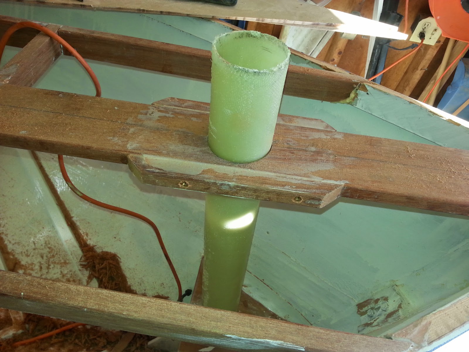
completed mast tube.
The center thwart had one screw in the way of the mast hole!  Fortunately, it came right out with the frearson head screw bit #2.  

The tubes measure an OD of 2.803.  That is more than 2 3/4" but less than 3".  No one has a 2 7/8" hole saw, so had to order one.  Yes, I could have used the saber saw, but the hole saw will be much neater.  

1-15-15
Turned out that finding a 2 7/8 hole saw was harder than I thought, but my local Woodcraft store had a 2 7/8 Forstner bit in stock.  Took it home and realized it would not fit into the chuck of my handymans drill.  Therefore, borrowed a friends 1/2" Heavy duty drill to do the honors.  The first step is to make a guide from spare stock which will help keep the bit on track as it initially grabs the wood.  
2 7/8" hole drilled into a spare piece of 3/8" stock.  small sliver of trimmed mast ring is sitting in the hole to check for proper size.  Looks good.  
So far, so good.  will drill the bow and thwart holes in the morning.  
I will not be putting the alternate mast step in as I really dont want holes up in the cockpit.  With two reefs in the main and mizzen, it should be fine.  

1-16-15
Mast holes located and drilled.  
1.  Mark location with a punch and set drill and 1/4" template in place.  
2.  Drill out! 
3.  Use a curved rasp and drum sander to finish mizzen hole.  The 1 1/2" centerboard frame needs to be cut and the Forstner bit will not cut it properly.  (note:  I could have attached a small board under the thwart to help steer the bit, but thought of that too late in the process.  No harm done.)  I will be purchasing a set of microplanes for this kind of thing in the future.  

Voila! 

The bubble level shows that I have it set vertically at the moment.  Needs a 3 degree tilt. 

Mizzen step.  Test for fit.  Drain hole needs to be drilled for the step.  

There is plenty of play to adjust the angles, fore and aft, port to starboard.  A 2.5" mailing tube fits perfectly!


A little router work and the deck is cut away for the tube.  Deck wont be fastened until hatch and tubes are glued in place, plus combing needs to be cut to fit as well.  Poco a poco. 


March 1, 2015

Finally gave up waiting for the winter from hell to end.  For those reading this from afar, we have had over 100" of snow in 30 days, and we have had one day where the thermometer made it above freezing.  Just horrid boatbuilding weather.

Today, I took stock of the mast tubes from B+B and looked at the track and sails I ordered as well.  this inspired me to go out and set the boat level and get the mizzen step aligned.  It did take well over 2 hours to get the boat level with the bow 10" higher than the stern, but I believe it is good.  Will take a good look at all prior to screwing the mizzen step down to the keel batten.  Also took time to make the seat/floorboard supports look good.

This weather is going to break soon, and then the project will pick up speed.  Right now, just moving in the cold is the project.

mizzen step is marked, not glued


Major delays due to this stuff!  WAAYY too much snow this month, and COOOLLLLDDDD. 


Forward hatch frame being fitted.  no glue yet. 

3-12-15
the mizzen step has been glued and screwed in.  Sorry no photos as I needed to move FAST due to the amount of work to get done on the only warm day since October.  

At the top of the step, you can see the drain hole. 

Forstner bit was used to drill the thwart.  This was not easy as the CB trunk is in the way of the cut. 

March 27, 2015 
Finally got sick of the longest, coldest, snowiest winter on record for the Northeast US, and turned the heat lamps on in the boat and epoxied up the first layer of support for the mast tubes.  This locks the tubes in place permanently.  I angled them with a 20" level and a 1" block of wood attached with tape to the level.  Seems pretty straight.  Now the boat which had been leveled can be moved around again and I can get at some other stuff in the garage.  Hope to get it out in the daylight for cleaning next week.  It cant be winter forever.  

March 28th - Heaters on, and mast tubes glues in place. 
I ran out of patience waiting for it to warm up outside, so went and placed heat lamps in the boat to warm the areas getting epoxied and keep warm while it sets.  The lower sections of the masts were inserted into the tubes, and then the level placed on the forward side to measure a 1:20" angle by placing a 1" block 20" up on the level.  The sides were set plumb, then a visual by checking that the main mast and mizzen were on plane for and aft.  Unfortunately, I cannot do a side visual within the garage.  Photos below. 


The whole assembly can now be moved around without fear of knocking things out of alignment.  I will add Fiberglass tape to the areas tomorrow to create a beefy, permanent, attachment to the hull.  


March 29, 2015
Glassed the base and below deck portions of the mast tubes and made the holes for the alternate position for the mizzen.  Thinking that the rowing position is better with the mast temporarily moved up, and that I have have a better area for camping in the long run.  
alternate mizzen step.  Pretty easy to do after you have done the mizzen and main tubes.  No tube needed as the deck and seating area will hold the mizzen in place firmly.  I will use a slice of extra mast tube to serve as a bushing at the deck level.  

mizzen step.  Will trim flush once the epoxy sets up. 

Main mast glassed in place and filleted with high strength filler. Drain tube needs to be added next.  

Better view of the mizzen step glassed in place.  Heat lamps are helping to kick off the glue.
Some more photos.
Alternate mizzen position.  Not much bother to put in. 

Cleaned boat ready to move on to some finish and trim work prior to putting the decks on permanently.

Center thwart with mizzen tube.  Some fairing and sanding is needed on the bottom step.

April 12, 2015
Mast tubes are all glued in place and the drainage tube installed from the bottom to the starboard forward quarter.  I used 1/4" drip irrigation tubing covered in cork grease for the mold and ran it through a 1/2" hold on the starboard quarter.  The thinking is that the plywood will be sealed by the epoxy filler.  Good in theory, but epoxy did not get into the bottom 1/2 of the exterior hole so will need to fill it from the outside.  The main tube could use a little more reinforcement, so will add a little more glass to the step prior to putting the deck on.  

this runs right from the bottom of the tube to a little below the mast step.  

A little sanding and painting and I am done with the mast tube drain.  Boat needs sanding anyways!

Read More..

Sabtu, 23 Juli 2016

Well, the title kinda says it all. So, lets get right to the pictures:


Here is the trimmed rear thwart, waiting for its first "finish" coat of epoxy on top. The plan was to mix some epoxy, coat the thwart using a thin foam roller, squeegee it, then thicken the rest of the epoxy with silica for attaching the forward thwart permanently.

I taped off areas on and around the forward thwart, to both mark where to place thickened epoxy and to make clean-up go more smoothly.

As you can see, there is a considerable gap between the thwart and the side of the hull on the starboard side. The gap is several inches long & gets progressively wider aft. The joint at the forward edge is considerably better. I knew it would take big globs of VERY thick epoxy to fill this gap.

The gap on the port side wasnt so bad.

First epoxy coat rolled & sqeegeed onto the aft thwart.

Heres that big gap filled with thickened epoxy. Before removing the tape, I used the curved corner of the squeegee to shape the epoxy edges.

Improvised bracing to help make sure the thwart was pressed down solidly and level.

Improvised bracing to help make sure the thwart was pressed down solidly and level.

I wanted to get a photo of this filled gap before I painted over it. This is from where I had to remove some material from the corner of the outer sheer lamination in order to get it to bend into place. I removed a little too much, leaving this gap. During installation of the sheer, I heaped on the thickened epoxy in order to fill it. This is the port side joint between the sheer and transom.

First layer of the AquaGard 190 primer on the port sheer.

First layer of the AquaGard 190 primer on the port sheer.

First layer of the AquaGard 190 primer on the port sheer.

Read More..