Kamis, 31 Maret 2016

Crisp Transom Edge

Ken Hankinsons excellent book, "How to Fiberglass Boats," suggests radiusing the hard edges of the hull in order to properly apply fiberglass cloth, without air bubbles forming underneath. The air bubbles would become a potential source of water entrapment, and inevitably... rot. Good motivation.

The book states that fiberglass cloth does not easily, or readily, adhere to sharp edges, but rather forms a curve.

Now, I wont begin to compare myself to the brilliant and accomplished Mr. Hankinson. He is the established expert, (that book and DVD are worth every penny... and then some). I myself, on the other hand, am stumbling toward completion of my first boat. However... I will mention this from my limited personal experience:

I used rather light fiberglass cloth (6 oz) on my little boat. And yes, I did radius the edges beforehand. From what I saw, light fiberglass cloth like that was very pliable when wetted out with epoxy. Enough so that I think it would conform to edges such as a chine junction or the base of a transom.... edges less than a 90° angle, that is. Id be less inclined to feel that way about heavier cloth, but light cloth like 6 oz, I THINK might conform to a sharp edge reasonably well. THIS IS A THEORY. I HAVE NOT TRIED THIS MYSELF. However, I think it is at least worth an initial attempt, and I will probably do so later on, on the Zip.

Why does all this matter?

As the book states, "The well-radiused corner required for proper application of fiberglass cloth is not desirable on some areas of certain types of boats. For example, the bottom edge along the transom of high performance boats or the inside edges along sponsons of hydroplanes should have a hard crisp corner for ultimate speed and performance..."

The book then goes on to describe how to create a "crisp" edge with additional layers of fiberglass cloth. I wont get into that method here, because I didnt use it. However, again... I do certainly recommend buying the book (and DVD!).

Now, my little boat with its 8hp motor is anything but a high performance speed boat. However, I still wanted to create a crisp transom edge. I simply did it with thickened epoxy... System Three Gel Magic in a cartridge with a mixer nozzle to be specific. Will it be durable enough to last? Time will tell.


Radiused edge along the chine and base of the transom.

Here, Ive taped poster board along the edge to create a form for the epoxy to fill in.

After clearing away the tape, poster board, and a lot of sanding, (it was an unholy mess!)... the base of the hull looks like this.

Heres the crisp epoxy edge at the base of the transom & along the chine.

I will have to clean up these scuff marks on the transom.

A mishap with the tape allowed epoxy to leak out & flow down the transom in one spot. I was able to scrape most of it away while it was still liquid, but Im still left with more "mess" to sand off of the transom.

If you try this method, keep a close eye on the progress in case of mishaps like this one. It couldve been a MAJOR problem if that runoff epoxy had cured.

This is the view along the port chine, where the radiused edge transitions to the filled-in, sharper epoxy edge.


Read More..

Selasa, 29 Maret 2016

The Utility Fiberglassing continues

I left off at the last post discussing "feathering" the edge of the fiberglass-covered area. This is simply sanding the edge down in order to have a smooth overlapped seam when you add the next, neighboring section of fiberglass cloth.

With 70% of the boats bottom covered, I feathered the forward edge of the fiberglassed area. I also rounded over the sharp edge on the bow. With this done, I was ready to add the next section of fiberglass cloth: covering the forward bottom on the port side of the hull.

It went very smoothly. Again, I highly recommend Ken Hankinsons book How To Fiberglass Boats, as it (and the accompanying DVD) make the process very easy to understand. 

Working alone, its difficult to photograph the fiberglassing process because Im mostly preoccupied with handling the epoxy (which I dont want to get all over my camera with messy, gloved hands). However, this time Ive tried to better show what some of the stages look like:


Photo from the previous post, showing the partially-feathered edge at the chine transition joint.
The same area after the new section of fiberglass cloth was added. On the left, you can see the edge of the new overlapping section. This will need to be sanded as well, to make the overlapping seam smooth.
Feathering the edge that has overlapped the bow.

Fiberglassed transom, after a 2nd coat of epoxy (squeegied meticulously) to fill the weave of the 6oz fiberglass cloth.

Read More..

Senin, 28 Maret 2016

motor well

This is a modification from the plans.

With the stern deck on, I added a small well for the motor on the port quarter.  I had one on a Herreshoff Goldeneye from Cape Cod Shipbuilding and loved that it put the motor right at hand, but did not interfere with normal operations.  I am to put a 2.3 or 2.5 longshaft motor on it.  I got the measurements off my 9.9 Johnson for a test fitting, so I am sure the smaller motor will not present issues.  Drain holes are oversized, and will be filled with epoxy putty then redrilled to size to help prevent water migration into the transom.  Varnish will be nice as well.


I purchased a 3.5 hp Tohatsu for it.  Fits good. 


Read More..

Sabtu, 26 Maret 2016

Five days until the G9 Boatbuilders Gathering.

I think I mentioned in an earlier post that, I never intended for this boat to have more than a "workboat" quality finish. In many ways, this project has been more about wanting a boat, and proving to myself that I could build one. A blue-ribbon, classic boat show museum piece, she was simply never meant to be. 

So, aside from trying to do the best job I can on a bright-finished transom and foredeck, Ive accepted the rest of the finish to be, well... rough around the edges.

Still, some of those epoxy runs on Frame #2 were just irritating me. So, today I decided to sand them off, (or at least down), since I was already going to paint another coat over it, anyway.


Epoxy runs sanded off of Frame #2.

The underside of the breasthook needs some more paint, too

Theres still a lot of work to be done, just to get the boat ready to travel... let alone for her to be finished. But, shes getting closer. Perseverance is a work in progress. 

I guess we all are, each in our own ways.

Ill close with a quote from James, one of Jesus brothers:

"Let perseverance finish its work, so that you may be mature and complete, not lacking anything."

James 1:4 NIV
Peace.
Read More..

Selasa, 22 Maret 2016

G9 minus six

Six days until G9. No major updates today, but I did want to keep the whole "countdown" theme going...


Today, my Perko oarlocks arrived from Jamestown Distributors. As with the Perko bow chocks I bought, I was happy to see that the oarlocks are also made here in the USA. Im not sure what happened to the oarlock sockets I ordered along with them, though...

Why oarlocks? I just wanted to have the rowing option. Some lakes at State Parks, etc, where I like to go dont allow outboard motors.

Also, tonight I drilled the hole in the transom knee for the stainless steel eye bolt. The eye bolt will secure a safety line that should prevent the outboard motor from sinking to the bottom of the river, should it vibrate loose from the transom. 


Actually, both the eye bolt, as well as the type of oarlock sockets I ordered, are ideas I borrowed from the Glen-L Utility that I got to see and drive at G8.

Glen-L Utility
This Glen-L Utility at G8 has both an eye bolt mounted in one of the transom knees, as well as edge-mount oarlock sockets.
Read More..

Senin, 21 Maret 2016

The Utility part 4 The Chines

Read enough boatbuilding blogs or forum threads, and youll find a commonly recurring theme: broken chine logs. Id read this so many times, that before starting my own I fully expected to break at least one. This is the major reason why I chose to use a less expensive material than mahogany for this part of the boat, particularly since the chines needed to be made from a full 12-foot length of board. 

With southern yellow pine prices locally being 1/5 the cost of mahogany, it seemed like a good choice. I just cant afford to be breaking 12 pieces of mahogany. (If you can, go for it. I think most would agree that mahogany is a superior boatbuilding wood). White oak is another good substitute, but there again, the southern yellow pine is substantially more affordable locally. Not only that, but Glen L Witts Boatbuilding With Plywood has some good things to say about southern yellow pine, including the statement that its frequently substituted for white oak.

For my part, Im glad I chose southern yellow pine. The wood bends very easily. I got started on the chines in late January 2013.

February suddenly found me lying in a hospital bed, waiting on an open slot for heart surgery. Not a pleasant position to be in. Since my doctors considered my case too high-risk to even let me walk the hallways before surgery, I occupied my time with Howard I. Chapelles Boatbuilding: A Complete Handbook of Wooden Boat Construction, John Gardners The Dory Book, and the latest issue of Wooden Boat Magazine. (When I said I was hooked on boatbuilding, I meant it.) Many of the fine medical staff who were looking after me were curious about my boatbuilding books & interest.

Before, during, and after the surgery, I was blessed with an outpouring of support from my family and friends, a multitude of prayers, visits from my church priest, and a visiting priest on Ash Wednesday. I tell you, it is an amazing and very humbling experience to be on the receiving end of the power of prayer. To witness its effects firsthand is simply dumbfounding. I have been blessed with a speedy recovery. I was able to walk unassisted the day after my surgery.

By March, while recovering at home, I was back to work on the chines. Basically, this involves:
1. Beveling the notch in the forward frame; 
2. Bending and clamping the chine log into position; 
3. Cutting the bevel at the forward end of the chine;
4. Fitting the aft end of the chine to the transom;
5. Fastening the chine into place with marine epoxy and bronze screws.

Chine logs roughly bent into their general position.

Initial bevel cut on forward end of chines.

I broke one of the chine logs while clamping it into its fully-bent position. While southern yellow pine indeed bends very easily, it does have its breaking point (literally). Most chine breaks occur near the forward frame, where the bend in the wood is greatest. I ripped another 2" x 12 piece with a handsaw and clamped it into place. Before bending it fully, I soaked the wood with hot water-soaked towels wrapped around it. I also applied as much steam as I could, using my steam iron.

Once the chine logs are bent into place, you cut the bevel at the forward end of the chine, using the vertical side surface of the stem as a guide. This gives a good approximation of the final bevel, but it needs to be cut again after the chine log is moved backward into its final position. Moving the chine backward changes the angle of the bend from the forward frame to the nearer end-point. The chine log is moved backward some because the forward tip of the chine is fitted a few inches short of the forward edge of the stem. This is so that the forward edge of the stem can be beveled so that the line of the chine curve continues forward to a sharp point on the bow. I had to make several additional cuts to the forward chine bevel in order to get the best fit. I used a 1/4" plywood spacer as a guide for my back saw, and this proved to be quite effective.

This is the gap that is created after repositioning the chine rearwards. This gap makes it necessary to re-cut the bevel.

Using a piece of 1/4" plywood as a guide helped greatly in getting the bevel cut correctly.


The aft end of the chine log is cut and fit after the forward end. Fitting the chine to the transom is very similar to fitting the floor battens. A little beveling with a rasp and file will do the job.

Once the chine logs are cut and fit to their final shape and position, they are fastened into place with thickened marine epoxy and bronze screws. I followed Glen-Ls recommendation to only use epoxy (not screws) at the junction of the chine to the forward frame notch. This is to avoid weakening the chine log at the point where it is most likely to break. Another technique Id recommend is to temporarily clamp a guide into place on the side of the stem. This guide will serve as a "ledge" on which to rest the forward end of the chine when you bend it back into position for final fastening. It will help with alignment of the chine to any holes you may have already drilled through it and into the stem. These can be rather tricky to find with thickened epoxy slopped all over the place. 

A simple guide clamped into position like this can help align your chine log with any pre-drilled holes in the stem. Otherwise, it can be difficult to match "hole-to-hole" with epoxy covering everything.


Forward end of chine attached to stem. Epoxy was thickened with mahogany wood flour.

Chine-to-forward-frame connection.

Chine-to-forward-frame connection.

Chine-to-frame-1 connection.


Chine-to-transom connection.
 
Chine-to-stem connection after sanding & initial fairing.


Chine-to-transom connection after sanding & initial fairing.
Read More..

Minggu, 20 Maret 2016

Building form in place

Thanks to Phil Gartlands generosity, I am the proud owner of a 12x4 x2 steel building form for the CS17.  It is now waiting for the load of plywood.  Going with bs 1088 okoume throughout. 


Read More..

Keel

August 28, 2014

Being tired of sanding, I switched gears to the keel.  The idea is to start with a lot of wood and wind up with a little less.  The keel on this boat is designed to take the weight of the boat on and off the trailer, proved something to hit a beach with, and add a little more stiffness to the hull.  (additionally, it will help track the boat with the centerboard retracted).

The plans have some conflicting information.  On the instruction sheets, the keel is described as being 3/4" and on the plans it measure 1"x1".  I went with this as I can always make it smaller, but not bigger if needed.
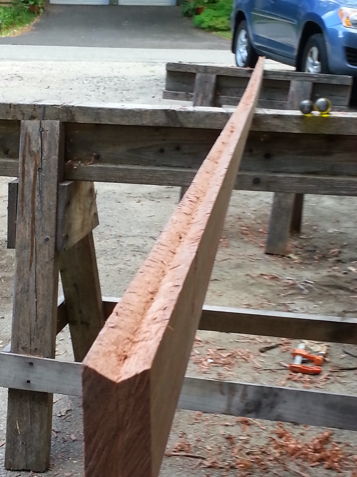
It took a few times of reading through the description of how to scribe the keel until I saw it clearly as to what should happen.  Basically, take a 1X2 plank (in my case, mahogany), and scribe a line down the middle.  Then place the 14 foot plank edgewise on the hull, with a helper holding it down against a block the same thickness as the keel.  Now, take another block of similar dimension and scribe a line along the board from the stern until it meets the other lines that mark the forward part of the plank.  I wish I took a photo, but the plans describe it well enough.  You are left with a plank that is 2" wide at the stern and tapers to 1" about 4-6 forward of that.  When it is all cut out, the plank will lie relatively flat against the hull, while the last 6 of the keel are straight.  The forward part will need to be shaped for better hydrodynamics as a blunt block is not too terribly efficient as shape.

Then, you need to cut a groove into the entire thing so that it fits flush against the hull.  All this will be held in place with screws and goop.  A final step is to fair it into the hull with fairing compound and then add a stainless rub strip to the bottom and chine edges.  These are to be sacrificial in nature.  Cutting the groove is a chore and I am sure there are power tools that could do it.  My method was to cut a 1/4" X 1/4" deep groove from stem to stern along the keel bottom with a chisel,  This is followed up with a 3/8" chisel to enlarge it.  Next, I knock down the sides of the V with a sharpened block plane.  Everything is then shaped up with the 3/4" chisel to make the V consistent.  This took two hours.  One hour was spent figuring out this method.  The other hour of actual consistent work.
V groove from stern to stem.


Tools used to cut the V groove 

Keel set temporarily in place to see how it fits.  Like a glove is the answer!


The sad news is tomorrow it is back to more sanding and filling until the boat is paint ready.  

Update - 9-4-14
We finally have the keel in place.  After working upside down from the inside while my daughter aligned the keel on the outside, we got all the temporary screws in place to prep for the application of the epoxy filler and glue.  It was at this time, my daughter asked a poignant question, "Why dont we put the boat on its side for this, it would be way easier, yes?"  So we rolled it off the cradle on onto its side.  And yes, it is way easier.  photos below. 
Boat is rolled out the garage yet one more time.  Keel is temporarily held in place with drywall screws.  
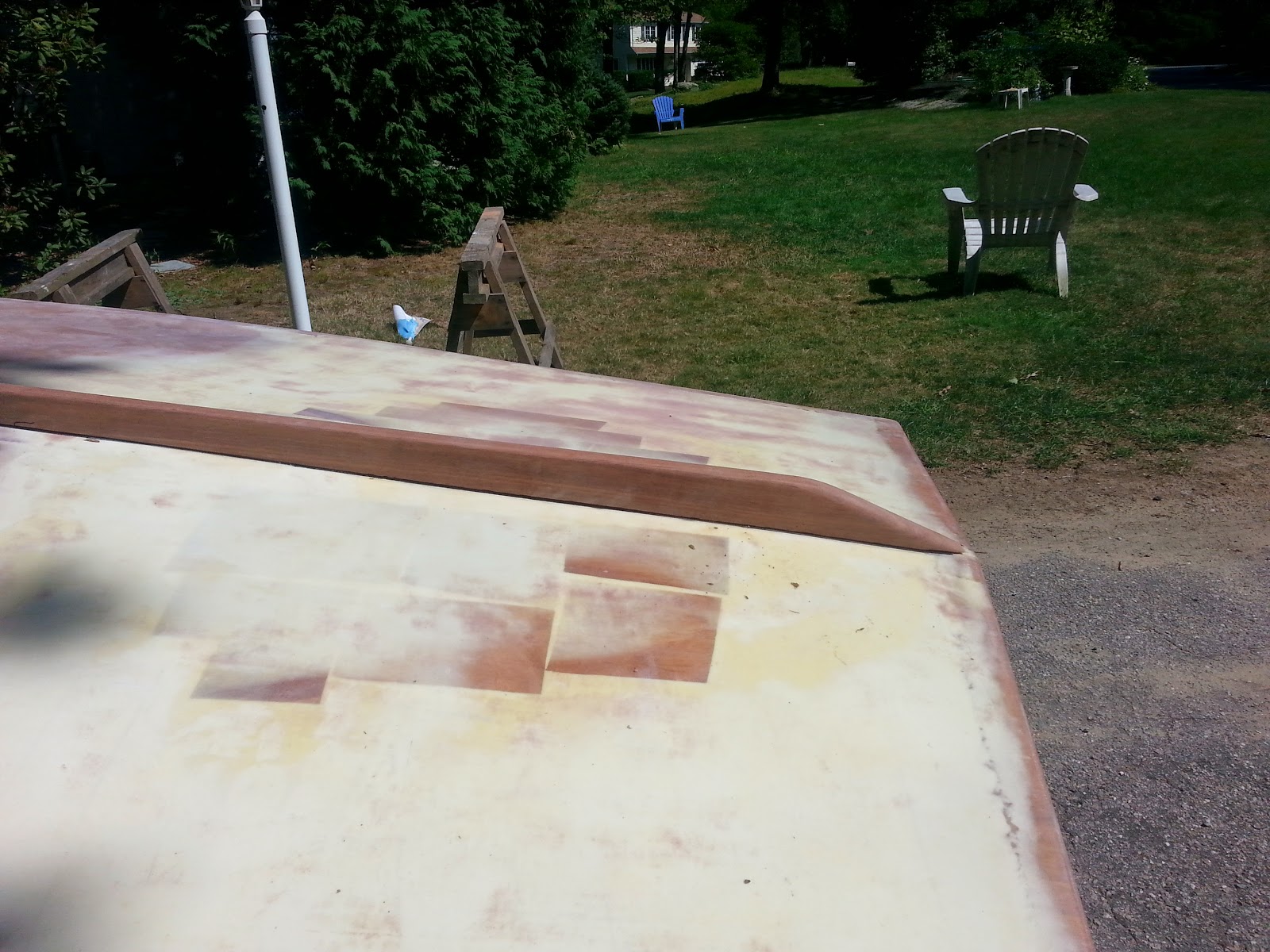
Keel has been shaped to final profile and aligned with a sharpie marker marking both sides.  
Screws are sticking pround of the forward part where the keel tapers,  holes and front get blended into hull so this will not be an issue.  No one will see it when the paint drys. 

We move the boat off the cradle by moving the bow off the cradle so that one side is still in contact with the cradle, and then the stern. An easy tip to vertical from there.  The boat is supported by two stout sawhorses.  


These sawhorses do the trick!  


Katie applies epoxy grout to the V groove.  I am the mixer in the garage, making more batches of grout.  
After the grout has been applied, I work the electric drill from this side, while Katie ensures the keel is aligned with our sharpie marks.  

This is the finished product, We will let it set overnight and then i will remove the drywall screws.  


Sept 5, 2014
We tilted the boat back on its side (son helped on his way to work), and I removed the screws.  Then, replaced the boat on the form and did some clean up and final shaping of ends.  It came out nice.  Paint is ordered.  Next, is the CB gasket (not on the plans).  

Read More..